Complete Software Solution for Unattended Automation of Complex AV Systems

Description
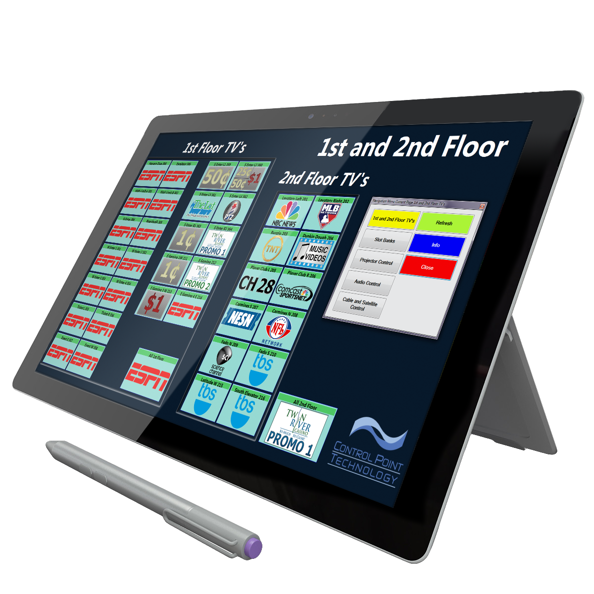
Control Point (CP) software is a complete solution that connects to all kinds of external devices such as signal matrix routers, displays, media servers, audio processors or any device with an RS-232, infrared or ethernet control interface. The CP client is a virtual control panel that allows non-programmers to customize the look and function of control buttons. CP client also allows non-programmers to create custom macros and scripts, manage or define external event triggers, and perform on the fly scheduling for complete unattended automation of complex audiovisual systems. Typical users include casinos, race tracks, educational campuses, hospitality, sports and entertainment venues, corporate conference rooms, cable TV head-ends and broadcasters.
Functional Design
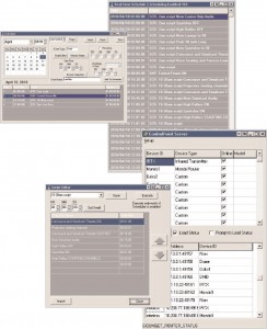
CP software has two components: CP client and CP server. The client-server architecture of CP provides the flexibility and scalability needed for any size facility regardless of location by utilizing the web.
The CP server can manage any number of external devices as long as they are accessible by a direct physical link from the CP server PC I/O port or remotely through ethernet device servers across the LAN or WAN. Each device is uniquely addressed by a user selectable name, such as ‘AV Router’. The server maintains a record of each device’s status.
The CP client runs on any PC that has network access to the CP server – including Wi-Fi connections. This design allows multiple concurrent CP client connections to a single CP server and management of all connected target hardware devices. All changes
automatically update the CP server status record and are immediately broadcast to all connected CP clients. Newly connecting CP clients are automatically updated to current status. An outstanding feature of the CP client is its highly customizable and rich graphical display that allows you to create virtual panels tailored just for you. The CP client uses pages that are populated with individual control buttons. All pages and buttons are customizable for each client and not limited in quantity. Buttons may represent a command, a device or both, and can execute simple actions or complex macros. Device buttons display status information to aid in confirmed operating control.
 Features
- Rich graphical virtual panel interface
- Highly customizable virtual panels
- Sophisticated Scheduler
- No programming skills required
- Complete unattended automation
- Advance macro functions
- Real time status for each device
- Configurable external event trigger (allows for Emergency Alert System (EAS) style programming)
- Client-server network compatible design
- Support for multiple concurrent clients
- Instant broadcast to all targets
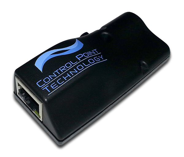
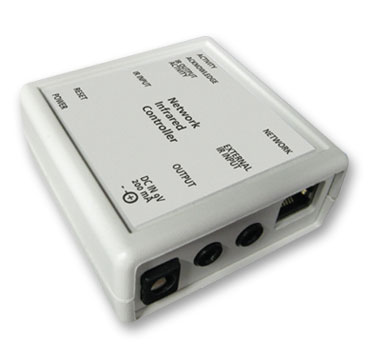
- Optional control hardware for infrared control across RF or IP networks
- Comprehensive event logs and traffic reports
- Pre-built IR and serial libraries
Users
- Casinos
- Racetracks
- Hotels
- Cruise Ships
- Schools
- Multi-Media Rooms
- Sports Bars
 Description
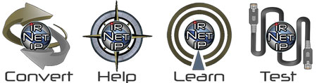
 Description
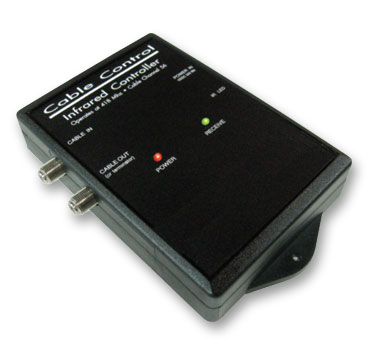 Description
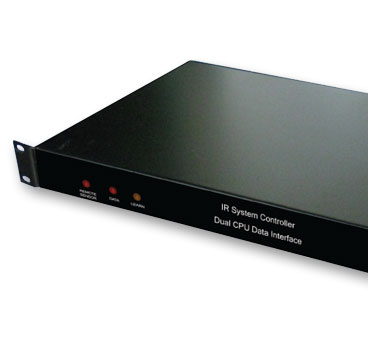 Description
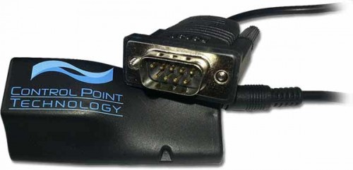
